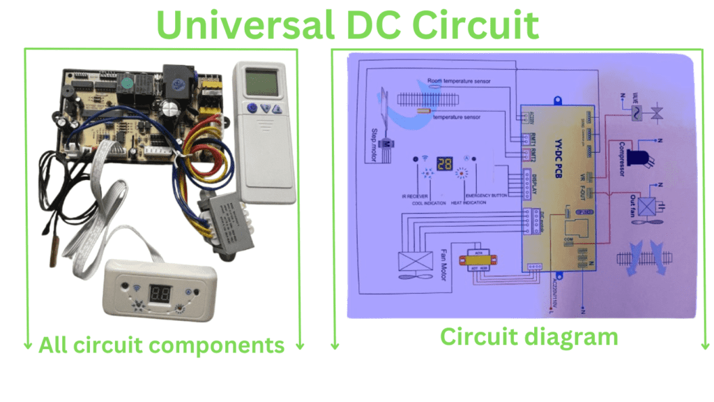
Universal DC Circuit


Introduction
If you are an AC technician then it is very important for you to know about Universal DC Circuit. It can make your work much easier .Sometimes you face AC circuit problems .Then you may need this DC circuit .A Universal DC circuit that uses AC power typically refers to devices or circuits designed to operate on AC power while incorporating a DC circuit for specific components or functionalities. This can involve converting AC to DC or employing DC within an AC-powered system. Here’s how this works
How DC Circuits Work
AC power input
The circuit is powered by an AC source, usually from the mains ( 120V or 230V AC).
AC to DC conversion
To use DC components, the AC input is converted to DC using components such as:
Rectifier: Convert AC to DC by allowing current to flow in only one direction ( a diode bridge rectifier).
Capacitors: Smooth the rectified voltage to reduce ripple, creating a more stable DC voltage.
Voltage Regulator: Ensure consistent DC voltage levels for sensitive components.
DC circuit components
After conversion, DC power can be used to:
Motors (like universal motors): These can work with both AC and DC due to their design.
Electronic Control Board: Found in machinery and devices for precise operation.
LEDs or Sensors: Requires stable DC voltage for operation.
Why use AC input?
Availability: AC is the standard for power transmission and distribution.
Efficiency in Transmission: AC is more efficient for transmitting power over long distances.
Versatility: By using rectification, AC can be easily converted to DC for specific applications.
Example:
Many household appliances, such as fans, blenders or drills, use universal motors, which can operate on AC or DC. The inner circuit transforms or conditions the input as needed. Similarly, many electronic devices such as TVs or laptops use an AC adapter to supply DC power to the internal circuitry.
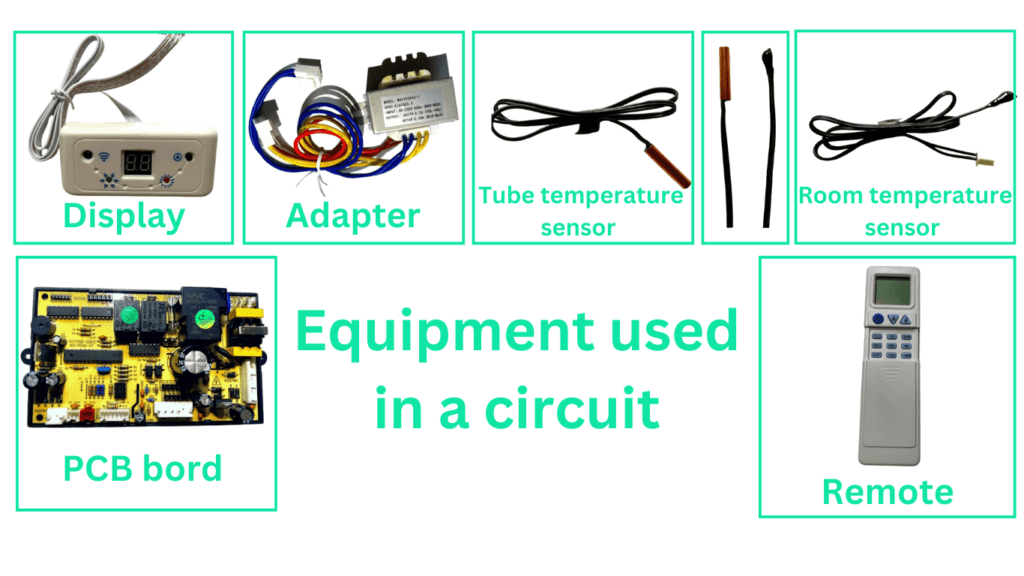
Equipment used in a circuit


Display
Building a universal DC circuit demonstration usually means building a versatile educational tool or diagnostic system that visualizes and demonstrates the behavior of DC circuits. It may include various components such as resistors, capacitors, inductors, diodes, LEDs and other DC circuit components. Here is a conceptual design for such a display:
Featur
- Adjustable DC voltage supply ( 0–30V).
- Multiple output terminals for different voltage levels.
- Circuit Components:
- Resistor of different quality.
- Capacitors with different capacitances.
- Inductors for basic RL circuits.
- LEDs and diodes for directionality and voltage drop sensing.
- Switch and Potentiometer:
- Toggle switch to connect/disconnect.
- Variable resistor/potentiometer for adjusting circuit parameters.
- Meter:
- Voltmeter and ammeter (digital or analog) for real-time monitoring.
- A multimeter for advanced measurements.
- Index:
- LEDs for power status and flow indicators.
- Buzzer for overcurrent or short-circuit warning.
- Connections:
- Breadboard for temporary setup.
- Banana plug connector for fast and reliable connection.
- Safety Features:
- Overcurrent protection (fuse or circuit breaker).
- Reverse polarity protection.
- Display Panel:
- LCD/LED screen to show circuit parameters and configuration.
- Digital visualization of circuit path (optional touchscreen for interaction).
Example circuit for demonstration
Diode Circuit: Simple rectifier circuit or a diode as a switch.
Basic DC Circuit: Power Supply -> Resistor -> LED.
Voltage Divider: Two resistors in series to demonstrate voltage division.
RC Circuit: Resistor and capacitor for charging/discharging visualization.
RL Circuit: Exhibiting inductive kickback.
Adapter
A universal DC circuit adapter is a versatile device designed to provide an adjustable DC voltage output for powering or testing a variety of electronic devices and circuits. These adapters are especially suited for technicians and hobbyists working with various devices that require specific voltage and current levels.
Tube temperature sensor
A tube temperature sensor is an important component for an air conditioner that is used to monitor the temperature of the refrigerant flowing through the copper tubes. This sensor is essential for controlling the cooling process and ensuring that the AC works effectively. Below are some key details:
- Working of a Tube Temperature Sensor**
- Monitor Refrigerant Temperature: Measures refrigerant temperature to ensure optimum performance.
- Protect Compressor: Prevents overheating by detecting irregularities in refrigerant temperature.
- Energy Efficiency: Helps adjust cooling cycle for better energy consumption.
- DEFROST FUNCTION: In heating mode (for heat pump), it helps to detect when defrosting is required.
Types of Tube Temperature Sensors
- Thermistor Sensor:
- Most commonly used.
- Resistance changes with temperature, providing precise readings.
- Type: NTC (Negative Temperature Coefficient) or PTC (Positive Temperature Coefficient).
Room Temperature Sensors
Room temperature sensors for air conditioning systems play an important role in maintaining the desired indoor climate by measuring and controlling the temperature. These sensors come in different types depending on the application, accuracy and budget. Below are the most common types used in AC systems:
